Project Pisces
Analytical Update
Due to the complex functionality of this concept, there will be a variety of relevant theory that will contribute to the engineering design analysis of the product. The structural integrity will be an important aspect to focus on during primary iterations of the design process. The design constraints in section 2.5 will require the analysis of how the material will perform under different working loads. At different velocities, depths, and pitch, the joints that connect the pylon to the bodies may undergo relatively large bending moments. To give an initial idea of robustness, the solid modeled component will forgo Finite Element Analysis in Autodesk Inventor software. If the part shows significant deformation or failure within a certain range of applied loads, there will be design iterations that must be performed. With respect to the major components of the design, namely the dual-tail and dual-fin mechanisms, large focus of design theory will be focused on the thrust and lift computations of these parts. The fin will be designed based on the cross-section, focusing on airfoil theory to maximize lift. Once the desired cross-section is achieved, a size and scale based on the chord length of the airfoil will be analyzed. This is analyzed in order to assess the Reynolds Number associated with the size of the prototype. The most important design analysis will focus on the thrust estimations from the robotic caudal fins. These will be analyzed in a Matlab program which inputs frequency, amplitude, desired freestream velocity, and fin area, outputting thrust force. Many of the parameters will revolve around increasing thrust, with interest given to the Strouhal Number generated by the fins. Fish in nature swim while maintaining a specific range of Strouhal Numbers, which has been correlated to maximizing thrust generated by eddy vortices. The thrust is a direct function of the angular position of the tail and the fin, so maximum thrust corresponds to the maximum difference in angular position. Once the theoretical parameters are optimized, this theory will be implemented into several servo motors which will simulate the required motions. Arduino software will be used to program the servo motors to oscillate in sinusoidal motions, with the fins and tails being 90 degrees out of phase in order to maximize the generative force. All theories will be empirically tested in a swimming pool, which will analyze the vorticy motions created by the prototype. To do this, PIV flow visualization will be implemented.
Economic Analyses
Throughout the duration of the design process, material optimization was a primary focus as to reduce not only the cost of the required material to create the parts as well as the power consumption required for the subsequent printing of said parts. The decision to manufacture the product utilizing 3D printing as opposed to traditional methods of manufacturing was done so as to reduce the cost incurred with requiring skilled labor. Implementing simplicity in regards to the design of the assembly process allows for a reduction in the labor cost as the unit manufactured will consist of an assembly kit. Current cost analysis projects the price point of $1,500 per unit to establish the break even point of total operational cost. With a projected price point of $2,000, each unit will incur a profit of approximately $500 for the first year, and subsequently increase almost twice the following year to around $970.
Additional steps may be taken in effort to further reduce cost. The equipment of choice is denoted as the model available in the design and manufacture of the prototype and does not necessarily have to comprise the manufacturing printers. Other models of 3D printers are available at a fraction of the cost, while yielding similar if not better results then the chosen model. The cost of purchasing equipment, and materials is comprised of the total cost of yielding one of the prototype units. It is expected that when operations are scaled, a reduction of cost will accompany higher quantities of purchase orders for the required products from their respective companies.
Environmental Analyses
The nature of the designed mimetic robot tuna demands real world resemblance in order to execute its main function of traversing aquatic environments alongside the natural wildlife. Components were chosen based on the criteria of the aforementioned product specifications in order to deliver on operational functionality. Environmental steps taken include utilizing a biodegradable plastic, minimizing of material in order to reduce power consumption.
Additional steps which may be taken to further its environmental sustainability include finding a more efficient and recyclable battery as well as increasing the aerodynamic flow to the design so as to decrease power consumption and reduce disturbance to the surrounding environment. Although electronic components of the product are not easily recyclable; proposed applications which include oceanic observance, pollution detection, marine ecological studies and numerous others, are expected to substantially outweigh the cost that the product will induce on the environment by the work conducted in preservation thereof.
Project Technical Progress Video
This is a Video of the testing for our Proof of Concept. It illustrates the motion that the tail of the Robotic tuna will be doing.
Boundary Conditions for Cylindrical Pylon
For this component FEA was conducted on the Cylindrical Pylon that connects each body of the fish together. A mesh was then applied to the part breaking up the complex geometry. A “worst case scenario” was applied to the part where one body is held still while the other experiences a max force. A fixed constraint was placed in the top left corner of the image on the surface where it meets the body, and a force of 1 pound was applied illustrated by the yellow arrow.

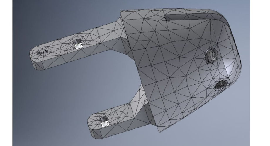
Boundary Conditions for Tail Fin Bracket
Similar to before, FEA was conducted on the Tail Fin Bracket. Once again, a mesh was created for the component. In this case what was of interest was testing the design of the bracket to see if it was at risk of failing and to make proper adjustments i.e. reducing weight, to optimize the component. Constraints were placed on the pin holes restricting the part in all directions. Followed by a pressure of 5 psi on the surface of the inner slot illustrated by the yellow arrows.
Tail Fin Bracket Displacement Deformation
All FEA was done using the material selection that will be used for printing. This material, as stated previously, is PLA (Polylactic Acid). Proper adjustments for physical and mechanical properties were done in the material choice in Inventor. From this analysis, factor of safeties can be found and with this, adjustments to the CAD files were made and are still being made to optimize each component.

Cylindrical Pylon Particle Flow
This analysis are the first steps that need to be taken when conducting CFD. In the near future, from these experiments fluid estimations will be obtained such as Lift and Drag force on the above parts. With this, changes can be made then tested again to see differences in results to optimize each part.
_edited.jpg)